
€69.11
Priemerné hodnotenie:0/5(0x)
Vlastnosti a parametre výrobku
Skúsenosti užívateľov
Otázky a odpovede
Dokumentácia
Popis
Vlastnosti a parametre výrobku
| Séria (domáca technika) | Homematic IP |
|---|---|
| Cloudová integrácia (Smart Home) | Alexa (je potrebná samostatná základná stanica) Google Home (je potrebná samostatná základná stanica) Conrad Connect (je potrebná samostatná základná stanica) |
| Bezdrôtové zariadenie (Smart Home) | Hersteller-Spezifisch |
| spínací výkon (max.) | 80 VA |
| Napájanie | 230 V |
| Prevádzkové napätie | 230 V |
| Frekvencia | 868 MHz |
| Max. dosah | 180 m |
| Spôsob montáže | Pod omietku |
| Vonkajšia šírka | 54 mm |
| Vonkajšia výška | 33 mm |
| Rozmer, hĺbka | 41 mm |
| Tok signálu (konektor A na B) | Obojsmerný (bi) |
| Kategória výrobku | Stmievací akčný člen |
Skúsenosti a názory zákazníkov
- Skúsenosti užívateľov nie sú k dispozícii.
Otázky užívateľov
- Užívatelia k tomuto výrobku zatiaľ nemali žiadne otázky.
Dokumentácia
Podmienky používania dokumentácie
1
Inhaltsverzeichnis 1 Hinweise zur Anleitung …22 Gefahrenhinweise …23 Funktion und Geräteübersicht …74 Allgemeine Systeminformationen …85 Inbetriebnahme …85.1 Installationshinweise …85.2 Installation …105.2.1 Installation in einer Unterputzdose …105.2.2 Installation in einer Aufputzdose …115.3 Anlernen …126 Fehlerbehebung …146.1 Befehl nicht bestätigt …146.2 Duty Cycle …146.3 Fehlercodes und Blinkfolgen …157 Wartung und Reinigung …178 Allgemeine Hinweise zum Funkbetrieb …179 Technische Daten …19
2
Hinweise zur Anleitung 1 Hinweise zur Anleitung Lesen Sie diese Anleitung sorgfältig, bevor Sie Ihr Home-matic IP Gerät in Betrieb nehmen. Bewahren Sie die An-leitung zum späteren Nachschlagen auf! Wenn Sie das Gerät anderen Personen zur Nutzung über-lassen, übergeben Sie auch diese Anleitung.
Benutzte Symbole: Achtung! Hier wird auf eine Gefahr hingewiesen.
Hinweis. Dieser Abschnitt enthält zusätzliche wichtige Informationen.
2 Gefahrenhinweise Öffnen Sie das Gerät nicht. Es enthält keine durch den Anwender zu wartenden Teile. Das Öffnen birgt die Gefahr eines Stromschlages. Lassen Sie das Gerät im Fehlerfall von einer Fachkraft prüfen.
Aus Sicherheits- und Zulassungsgründen (CE) ist das eigenmächtige Umbauen und/oder Verän-dern des Gerätes nicht gestattet.
3
Gefahrenhinweise Verwenden Sie das Gerät nicht, wenn es von au-ßen erkennbare Schäden, z. B. am Gehäuse, an Bedienelementen oder an den Anschlussbuchsen ausweist. Lassen Sie das Gerät im Zweifelsfall von einer Fachkraft prüfen.
Betreiben Sie das Gerät nur in trockener sowie staubfreier Umgebung, setzen Sie es keinem Ein-fluss von Feuchtigkeit, Vibrationen, ständiger Sonnen- oder anderer Wärmeeinstrahlung, Kälte und keinen mechanischen Belastungen aus.
Das Gerät ist kein Spielzeug! Erlauben Sie Kindern nicht damit zu spielen. Lassen Sie das Verpa-ckungsmaterial nicht achtlos liegen. Plastikfolien/ -tüten, Styroporteile etc. können für Kinder zu einem gefährlichen Spielzeug werden.
Bei Sach- oder Personenschaden, die durch un-sachgemäße Handhabung oder Nichtbeachten der Gefahrenhinweise verursacht werden, über-nehmen wir keine Haftung. In solchen Fällen er-lischt jeder Gewährleistungsanspruch! Für Folge-schäden übernehmen wir keine Haftung!
Das Gerät darf nur für ortsfeste Installationen ver-wendet werden. Das Gerät ist sicher innerhalb einer festen Installation zu fixieren.
4
Gefahrenhinweise Der Aktor ist Teil der Gebäudeinstallation. Bei der Planung und Errichtung sind die einschlägigen Normen und Richtlinien des Landes zu beachten. Der Betrieb des Gerätes ist ausschließlich am 230 V/50 Hz-Wechselspannungsnetz zulässig. Arbeiten am 230-V-Netz dürfen nur von einer Elektrofachkraft (nach VDE 0100) erfolgen. Dabei sind die geltenden Unfallverhütungsvorschriften zu beachten. Zur Vermeidung eines elektrischen Schlages am Gerät, schalten Sie bitte die Netz-spannung frei (Sicherungsautomat abschalten). Bei Nichtbeachtung der Installationshinweise können Brand oder andere Gefahren entstehen.
Beachten Sie beim Anschluss an die Geräteklem-men die hierfür zulässigen Leitungen und Lei-tungsquerschnitte.
Die am Ausgang angeschlossenen Verbraucher müssen über eine ausreichende Isolierung verfügen.
Vor dem Anschließen des Aktors muss die Siche-rung im Sicherungskasten herausgenommen werden.
Das Gerät ist nicht zum Freischalten geeignet.
5
Gefahrenhinweise Beachten Sie vor Anschluss eines Verbrauchers die technischen Daten, insbesondere die maximal zu-lässige Anschlussleistung des Dimmaktors und Art des anzuschließenden Verbrauchers. Alle Lastan-gaben beziehen sich auf ohmsche Lasten. Belasten Sie den Aktor nur bis zur angegebenen Leistungs-grenze.
Eine Überlastung kann zur Zerstörung des Gerä-tes, zu einem Brand oder zu einem elektrischen Schlag führen.
Der Stromkreis, an dem das Gerät und die Last angeschlossen werden, muss mit einem Lei-tungsschutzschalter gemäß EN60898-1 (Auslö-secharakteristik B oder C, max. 16 A Nennstrom, min. 6 kA Abschaltvermögen, Energiebegren-zungsklasse 3) abgesichert sein. Installationsvor-schriften lt. VDE 0100 bzw. HD384 oder IEC 60364 müssen beachtet werden. Der Leitungs-schutzschalter muss für den Benutzer leicht er-reichbar und als Trennvorrichtung für das Gerät gekennzeichnet sein.
Es dürfen nur dimmbare 230-V-LED-Leuchtmit-tel eingesetzt werden. Der Einsatz von nicht dimmbaren 230-V-LED-Leuchtmitteln kann das Gerät und/oder das Leuchtmittel zerstören.
6
Gefahrenhinweise Setzen Sie beim Betrieb mit elektronischen Trafos nur Transformatoren ein, die den Anforderungen nach DIN EN 61347-1 (VDE 0712-30, Teil 1) sowie DIN EN 61047 (VDE 0712-25, Teil 2) entsprechen.
Der Dimmaktor ist ausschließlich für Glühlampen sowie für Hochvolt-Halogenlampen und Nieder-volt-Halogenlampen mit konventionellen Trafos geeignet! Schließen Sie am Dimmaktor nur Lasten lampen und keine Fernseher, Computer, Motoren etc. an.
Der Dimmaktor enthält einen thermischen Schutz. Bitte beachten Sie, dass bei Überhitzung die Verbraucher ganz abgeschaltet werden.
Das Zuschalten von Lasten im eingeschalteten Zu-stand (Dimmlevel ungleich 0) ist nicht zulässig, da dadurch sehr hohe Einschaltströme entstehen können, die das Gerät zerstören.
Beim Betrieb mit 230-V-LED-Leuchtmitteln ist zu beachten, dass viele aufgrund der sehr niedrigen Stromaufnahme im ausgeschalteten Zustand zum Glimmen oder Aufblitzen neigen.
Das Gerät ist nur für den Einsatz in wohnungs-ähnlichen Umgebungen geeignet.
7
Funktion und Geräteübersicht Jeder andere Einsatz, als der in dieser Bedie-nungsanleitung beschriebene, ist nicht bestim-mungsgemäß und führt zu Gewährleistungs- und Haftungsausschluss.
3 Funktion und Geräteübersicht Der Homematic IP Dimmaktor eignet sich für die Montage in einer Unterputz- oder Aufputzdose. Einmal installiert dimmt und schaltet das Gerät angeschlossene Verbraucher wie Glühlampen, HV-Halogenlampen, NV-Halogenlampen mit elektronischem Trafo, dimmbare Energiesparlampen und viele dimmbare LEDs ein bzw. aus.
Der Dimmaktor ermöglicht das komfortable Dimmen und Schalten von angeschlossenen Leuchten per Funk-Fernbedienung oder über die Homematic IP App.
Geräteübersicht (s. Abbildung 1): (A) Fixieröse(B) Anschlussklemme für (gedimmte Phase)(C) Anschlussklemme für L (Phase) (D) Anschlussklemme für N (Neutralleiter)
8
Allgemeine Systeminformationen 4 Allgemeine Systeminformationen Dieses Gerät ist Teil des Homematic IP Smart-Home-Systems und kommuniziert über das Homematic IP Funkprotokoll. Alle Geräte des Systems können komfortabel und individuell per Smartphone über die Homematic IP App konfiguriert werden. Alternativ haben Sie die Möglichkeit, Homematic IP Geräte über die Homematic Zentrale CCU2 oder in Verbindung mit vielen Partnerlösungen zu betreiben. Welcher Funktionsumfang sich innerhalb des Systems im Zusammenspiel mit weiteren Komponenten ergibt, entnehmen Sie bitte dem Homematic IP Anwenderhandbuch. Alle technischen Dokumente und Updates finden Sie stets aktuell unter www.eQ-3.de.
5 Inbetriebnahme5.1 Installationshinweise Bitte lesen Sie diesen Abschnitt erst vollständig, bevor Sie mit der Installation beginnen.
Bitte notieren Sie sich vor der Installation die auf dem Gerät angebrachte Gerätenummer (SGTIN) und den Installationsort, damit Sie das Gerät im Nachhinein leichter zuordnen können. Alternativ steht die Gerätenummer auch auf dem beiliegen-den QR-Code-Aufkleber.
9
Inbetriebnahme Hinweis! Installation nur durch Personen mit einschlägigen elektrotechnischen Kenntnissen und Erfahrungen!* Durch eine unsachgemäße Installation gefährden Sie- Ihr eigenes Leben;- das Leben der Nutzer der elektrischen Anlage.
Mit einer unsachgemäßen Installation riskieren Sie schwere Sachschäden, z. B. durch Brand. Es droht für Sie die persönliche Haftung bei Personen- und Sachschäden.
Wenden Sie sich an einen Elektroinstallateur!*Erforderliche Fachkenntnisse für die Installation:Für die Installation sind insbesondere folgende Fachkenntnisse er-forderlich:- Die anzuwendenden „5 Sicherheitsregeln“: Freischalten; gegen Wiedereinschalten sichern; Spannungsfreiheit feststellen; Erden und Kurzschließen; benachbarte, unter Spannung stehende Teile abdecken oder abschranken;- Auswahl des geeigneten Werkzeuges, der Messgeräte und ggf. der persönlichen Schutzausrüstung;- Auswertung der Messergebnisse;- Auswahl des Elektro-Installationsmaterials zur Sicherstel-lung der Abschaltbedingungen;- IP-Schutzarten;- Einbau des Elektroinstallationsmaterials;- Art des Versorgungsnetzes (TN-System, IT-System, TT-System) und die daraus folgenden Anschlussbedin-gungen (klassische Nullung, Schutzerdung, erforderliche Zusatzmaßnahmen etc.).
10
Inbetriebnahme Die Installation darf nur in handelsüblichen Schal-terdosen (Gerätedosen) gemäß DIN 49073-1 oder Aufputzdosen gemäß DIN 60670-1 (z. B. Abox 025 oder Abox 040) erfolgen.
Beachten Sie bei der Installation die Gefahrenhin-weise gemäß „2 Gefahrenhinweise“ auf Seite 2.
Zugelassene Leitungsquerschnitte zum Anschluss an den Dimmaktor sind: Starre Leitung [mm2]Flexible Leitung mit und ohne Aderendhülse [mm2] 0,75 – 1,500,75 – 1,50
5.2 InstallationSie haben die Möglichkeit, den Dimmaktor- in einer Unterputzdose oder- in einer Aufputzdosezu installieren.
5.2.1 Installation in einer Unterputzdose Für die Installation des Dimmaktors in einer Unterputzdose gehen Sie wie folgt vor:- Schalten Sie die Haussicherung des Stromkreises ab.- Zur Versorgung schließen Sie den Aktor an L (C)
11
Inbetriebnahme und N (D) an (s. Abbildung 2).- Führen Sie die gedimmte Phase (B) zum Verbrau-cher (s. Abbildung 2).- Setzen Sie den Aktor in eine geeignete Unter-putzdose. Sie können die Fixieröse (A) bei Bedarf entfernen.- Schließen Sie die Unterputzdose mit einer geeig-neten Abdeckung.- Schalten Sie die Haussicherung wieder ein, um den Anlernmodus des Geräts zu aktivieren (s. „5.3 Anlernen“ auf Seite 12).
5.2.2 Installation in einer Aufputzdose Für die Installation des Dimmaktors in einer Aufputzdose gehen Sie wie folgt vor:- Schalten Sie die Haussicherung des Stromkreises ab.- Zur Versorgung schließen Sie den Aktor an L (C) und N (D) an (s. Abbildung 2).- Führen Sie die gedimmte Phase (B) zum Verbrau-cher (s. Abbildung 2).- Setzen Sie den Aktor in eine geeignete Aufputzdose (z. B. Abox 025 oder Abox 040) (s. Abbildung 3).- Setzen Sie den Aktor mit der Fixieröse auf dem Haltedom fest. Der Aktor muss ggf. festge-schraubt werden.- Schließen Sie die Aufputzdose mit der zugehöri-gen Abdeckung.
12
Inbetriebnahme – Schalten Sie die Haussicherung wieder ein, um den Anlernmodus des Geräts zu aktivieren (s. „5.3 Anlernen“ auf Seite 12).
5.3 AnlernenBitte lesen Sie diesen Abschnitt erst vollständig, bevor Sie mit dem Anlernen beginnen.
Richten Sie zunächst Ihren Homematic IP Access Point über die Homematic IP App ein, um weitere Homematic IP Geräte im Homematic IP System nutzen zu können. Ausführliche Informationen dazu finden Sie in der Bedienungsanleitung des Access Points.
Sie können das Gerät sowohl an den Access Point als auch an die Homematic Zentrale CCU2 anler-nen. Weitere Informationen dazu entnehmen Sie bitte dem Homematic IP Anwenderhandbuch (zu finden im Downloadbereich unter www.eQ-3.de).
Damit der Dimmaktor in Ihr System integriert werden und mit anderen Homematic IP Geräten kommunizieren kann, muss er zunächst an den Homematic IP Access Point angelernt werden.
Zum Anlernen des Dimmaktors gehen Sie wie folgt vor:- Öffnen Sie die Homematic IP App auf Ihrem
13
Inbetriebnahme Smartphone.- Wählen Sie den Menüpunkt „Gerät anlernen“ aus.- Nach der Installation ist der Anlernmodus für 3 Minuten aktiv.
Sollten die 3 Minuten bereits verstrichen sein, schalten Sie die Netzspannung aus und wieder ein, um den Anlernmodus erneut zu starten.
– Das Gerät erscheint automatisch in der Home-matic IP App.- Zur Bestätigung geben Sie in der App die letzten vier Ziffern der Gerätenummer (SGTIN) ein oder scannen Sie den QR-Code. Die Gerätenummer finden Sie auf dem Aufkleber im Lieferumfang oder direkt am Gerät. – Warten Sie, bis der Anlernvorgang abgeschlossen ist.- Zur Bestätigung eines erfolgreichen Anlernvor-gangs leuchtet die LED grün. Das Gerät ist nun einsatzbereit.- Leuchtet die LED rot, versuchen Sie es erneut.- Wählen Sie aus, in welchen Anwendungen (z. B. Licht und/oder Sicherheit) Sie Ihr Gerät verwen-den möchten.- Vergeben Sie in der App einen Namen für das Ge-rät und ordnen Sie es einem Raum zu.
14
Fehlerbehebung 6 Fehlerbehebung6.1 Befehl nicht bestätigt Bestätigt mindestens ein Empfänger einen Befehl nicht, leuchtet zum Abschluss der fehlerhaften Übertragung die LED rot auf. Grund für die fehlerhafte Übertragung kann eine Funkstörung sein (s. „8 Allgemeine Hinweise zum Funkbetrieb“ auf Seite 17). Die fehlerhafte Übertra-gung kann folgende Ursachen haben:- Empfänger nicht erreichbar,- Empfänger kann Befehl nicht ausführen (Lastaus-fall, mechanische Blockade etc.) oder- Empfänger defekt.
6.2 Duty Cycle Der Duty Cycle beschreibt eine gesetzlich geregelte Be-grenzung der Sendezeit von Geräten im 868 MHz-Be-reich. Das Ziel dieser Regelung ist es, die Funktion aller im 868 MHz-Bereich arbeitenden Geräte zu gewährleisten.In dem von uns genutzten Frequenzbereich 868 MHz be-trägt die maximale Sendezeit eines jeden Gerätes 1 % ei-ner Stunde (also 36 Sekunden in einer Stunde). Die Geräte dürfen bei Erreichen des 1 %-Limits nicht mehr senden, bis diese zeitliche Begrenzung vorüber ist. Gemäß dieser Richtlinie, werden Homematic IP Geräte zu 100 % nor-menkonform entwickelt und produziert.Im normalen Betrieb wird der Duty Cycle in der Regel nicht erreicht. Dies kann jedoch in Einzelfällen bei der In-betriebnahme oder Erstinstallation eines Systems durch
15
Fehlerbehebung vermehrte und funkintensive Anlernprozesse der Fall sein. Eine Überschreitung des Duty-Cycle-Limits wird durch ein langes rotes Blinken der LED angezeigt und kann sich durch temporär fehlende Funktion des Gerätes äußern. Nach kurzer Zeit (max. 1 Stunde) ist die Funktion des Ge-rätes wiederhergestellt.
6.3 Fehlercodes und Blinkfolgen BlinkcodeBedeutungLösung Kurzes oranges Blinken Funkübertra-gung/Sende-versuch/Daten-übertragung Warten Sie, bis die Übertragung been-det ist.
1x langes grünes Leuchten Vorgang bestätigtSie können mit der Bedienung fort-fahren.
1x langes rotes Leuchten Vorgang fehl-geschlagenVersuchen Sie es erneut (s. „6.1 Befehl nicht bestätigt“ auf Seite 14).
16
Fehlerbehebung Kurzes oranges Blinken (alle 10 s) Anlernmodus aktivGeben Sie die letz-ten vier Ziffern der Geräte-Seriennum-mer zur Bestätigung ein (s. „5.3 Anlernen“ auf Seite 12).
1x langes rotes Leuchten Vorgang fehl-geschlagen oder Duty-Cycle-Limit erreicht Versuchen Sie es erneut („6.1 Befehl nicht bestätigt“ auf Seite 14 oder „6.2 Duty Cycle“ auf Seite 14).
6x langes rotes BlinkenGerät defektAchten Sie auf die Anzeige in Ihrer App oder wenden Sie sich an Ihren Fachhändler.
1x oranges und 1x grünes Leuchten TestanzeigeNachdem die Test-anzeige erloschen ist, können Sie fortfahren.
17
Wartung und Reinigung 7 Wartung und Reinigung Das Gerät ist wartungsfrei. Überlassen Sie eine War-tung oder Reparatur einer Fachkraft.
Vor Ausbau des Gerätes unbedingt Netzspan-nung freischalten (Sicherungsautomat abschal-ten)! Arbeiten am 230 V-Netz dürfen nur von ei-ner Elektro-Fachkraft (nach VDE 0100) erfolgen.
Reinigen Sie das Gerät mit einem weichen, sauberen, trockenen und fusselfreien Tuch. Für die Entfernung von stärkeren Verschmutzungen kann das Tuch leicht mit lauwarmem Wasser angefeuchtet werden. Achten Sie darauf, dass keine Feuchtigkeit in das Gerät gelangt. Verwenden Sie keine lösemittelhaltigen Reinigungsmittel, das Kunststoffgehäuse und die Beschriftung können da-durch angegriffen werden.
8 Allgemeine Hinweise zum Funkbetrieb Die Funk-Übertragung wird auf einem nicht exklusiven Übertragungsweg realisiert, weshalb Störungen nicht ausgeschlossen werden können. Weitere Störeinflüsse können hervorgerufen werden durch Schaltvorgänge, Elektromotoren oder defekte Elektrogeräte.
18
Allgemeine Hinweise zumFunkbetrieb Die Reichweite in Gebäuden kann stark von der im Freifeld abweichen. Außer der Sendeleistung und den Empfangseigenschaften der Empfänger spielen Umwelteinflüsse wie Luftfeuchtigkeit neben baulichen Gegebenheiten vor Ort eine wichtige Rolle.
Hiermit erklärt die eQ-3 AG, dass sich dieses Gerät in Übereinstimmung mit den grundlegenden Anforderun-gen und den anderen relevanten Vorschriften der Richtli-nie 1999/5/EG befindet.Die vollständige Konformitätserklärung finden Sie unter www.eQ-3.de.
19
Technische Daten 9 Technische Daten Geräte-Kurzbezeichnung: HmIP-FDTVersorgungsspannung: 230 V/50 HzStromaufnahme: 0,35 A Minimallast: 3 VA Maximale Schaltleistung: 80 VA Leistungsaufnahme im Ruhebetrieb: 0,4 W Dimmverfahren: PhasenabschnittLastart: ohmsche und kapazitive LampenlastLeitungsart u. -querschnitt: starre und flexible Leitung, 0,75-1,5 mm²Installation: nur in Schalterdosen (Gerätedosen) gemäß DIN 49073-1 oder Aufputzdosen gemäß DIN 60670-1 (z. B. Abox 025 oder Abox 040)Schutzart: IP20Schutzklasse: IIGeräteschutz: Überlastsicherung, TemperatursicherungUmgebungstemperatur: 5 bis 35 °CAbmessungen (B x H x T ): 54 x 33 x 41 mmGewicht: 31 gFunkfrequenz: 868,3 MHz/869,525 MHzEmpfängerkategorie: SRD category 2Typ. Funk-Freifeldreichweite: 180 mDuty Cycle: < 1 % pro h/< 10 % pro h
20
Technische Daten Technische Änderungen vorbehalten.
EntsorgungshinweisGerät nicht im Hausmüll entsorgen! Elektroni-sche Geräte sind entsprechend der Richtlinie über Elektro- und Elektronik-Altgeräte über die örtlichen Sammelstellen für Elektronik-Altgeräte zu entsorgen.
KonformitätshinweisDas CE-Zeichen ist ein Freiverkehrszeichen, das sich ausschließlich an die Behörden wendet und keine Zusicherung von Eigenschaften beinhaltet.
Bei technischen Fragen zum Gerät wenden Sie sich bitte an Ihren Fachhändler.
21
Package contents QuantityDescription 1Homematic IP Dimming Actuator flush-mount – trailing edge 1Operating manual Documentation © 2017 eQ-3 AG, Germany.All rights reserved. Translation from the original version in German. This manual may not be reproduced in any format, either in whole or in part, nor may it be duplicated or edited by electronic, mechanical or chemical means, without the written consent of the publisher.Typographical and printing errors cannot be excluded. However, the information contained in this manual is reviewed on a regular basis and any necessary corrections will be implemented in the next edition. We accept no liability for technical or typographical errors or the consequences thereof.All trademarks and industrial property rights are acknowledged.Printed in Hong KongChanges may be made without prior notice as a result of techni-cal advances.
150615Version 1.0 (01/2017)
22
Table of contents 1 Information about this manual…232 Hazard information …233 Function and device overview …284 General system information …295 Start-up …295.1 Installation instructions …295.2 Installation …315.2.1 Flush-mounting box installation…315.2.2 Surface-mounting box installation …325.3 Teaching-in …336 Troubleshooting …346.1 Command not confirmed …346.2 Duty cycle …356.3 Error codes and flashing sequences …367 Maintenance and cleaning …378 General information about radio operation …389 Technical specifications …39
23
Information about this manual 1 Information about this manual Please read this manual carefully before beginning operation with your Homematic IP component. Keep the manual so you can refer to it at a later date if you need to. If you hand over the device to other persons for use, please hand over this manual as well.
Symbols used: Attention! This indicates a hazard.
Please note: This section contains important ad-ditional information.
2 Hazard information Do not open the device. It does not contain any parts that can be maintained by the user. There is a risk of electric shock if the device is opened. If you have any doubts, have the device checked by an expert.
For safety and licensing reasons (CE), unauthorized change and/or modification of the device is not permitted.
24
Hazard information Do not use the device if there are signs of damage to the housing, control elements or connecting sockets, for example. If you have any doubts, have the device checked by an expert.
The device may only be operated in dry and dust-free environment and must be protected from the effects of moisture, vibrations, solar or other meth-ods of heat radiation, cold and mechanical loads.
The device is not a toy; do not allow children to play with it. Do not leave packaging material lying around. Plastic films/bags, pieces of polystyrene, etc. can be dangerous in the hands of a child.
We do not assume any liability for damage to property or personal injury caused by improper use or the failure to observe the hazard information. In such cases, any claim under warranty is extinguished! For consequential damages, we assume no liability!
The device may only be used for fixed installations. The device must be securely attached within a fixed installation.
The actuator is part of the building installation. The relevant national standards and directives must be
25
Hazard information taken into consideration during planning and set-up. The device has been designed solely for operation on a 230 V/50 Hz AC supply. Only qualified electricians (to VDE 0100) are permitted to carry out work on the 230 V mains. Applicable accident prevention regulations must be complied with whilst such work is being carried out. To avoid electric shocks from the device, please disconnect the mains voltage (trip the miniature circuit-breaker). Non-compliance with the installation instructions can cause fire or introduce other hazards.
When connecting to the device terminals, take the permissible cables and cable cross sections into account.
Connected loads require sufficient insulation.
Before the actuator is connected, remove the fuse from the fuse box.
The device has not been designed to support safety disconnection.
Please take the technical data (in particular the maximum permissible effective installed load of the dimming actuator and the type of load to be
26
Hazard information connected) into account before connecting a load! All load data relates to ohmic loads. Do not exceed the capacity specified for the device.
Exceeding this capacity could lead to the de-struction of the device, fires or electric shocks.
The circuit to the which the device and the load will be connected has to be secured by a cable protection switch in accordance with EN60898-1 (tripping characteristic B or C, max. 16 A rated current, min. 6 kA interrupting rating, energy limiting class 3). Installation regulations according to VDE 0100 and HD382 or 60364 have to be considered. Users must be able to easily access the cable protection switch. This must be marked as disconnecting device for the actuator.
Only dimmable 230 V LED lamps may be used. Not dimmable 230 V LED lamps may destroy the device and/or the light source.
If the dimming actuator is operated with elec-tronic transformers, only those which meet the requirements of DIN EN 61347-1 (VDE 0712-30, Part 1) along with DIN EN 61047 /VDE 0712-25, Part 2) may be used.
27
Hazard information The dimming actuator is only suitable for light bulbs and high-voltage and low-voltage halogen lamps with conventional transformers! Please only connect lamp loads to the dimming actua-tor, and no televisions, computers, motors etc.
The dimming actuator contains a thermal cut-off. Please note that in the event of overheating the loads will be switched off completely.
Switching on of loads during power-on state (dim-ming level unequal to 0) is not permitted. Doing so may generate very high inrush currents that can destroy the device.
Please note that 230 V LED lamps may glow or flash while they are switched off due to the very low power consumption.
The device may only be operated within residential buildings.
Using the device for any purpose other than that described in this operating manual does not fall within the scope of intended use and shall invalidate any warranty or liability.
28
Function and device overview 3 Function and device overview The Homematic IP Dimming Actuator offers installation with a flush-mounting or surface-mounting box. Once installed, the device offers dimming and switching of connected loads such as classic incandescent lamps, HV and LV halogen lamps (with electronic transformer) and dimmable energy-saving lamps as well as many dimmable LED lamps.
The dimming actuator enables comfortable dimming and switching of connected lights via remote control or the Homematic IP app.
Device overview (see figure 1): (A) Fixing lug(B) Connecting terminal for (dimmed phase)(C) Connecting terminal for L (phase conductor) (D) Connecting terminal for N (neutral conductor)
29
General system information 4 General system information This device is part of the Homematic IP smart home system and works with the Homematic IP radio protocol. All devices of the system can be configured comfortably and individually with the Homematic IP smartphone app. Alternatively, you can operate the Homematic IP devices via the Homematic Central Control Unit CCU2 or in connection with various partner solutions. The available functions provided by the system in combination with other components are described in the Homematic IP User Guide. All current technical documents and updates are provided at www.eQ-3.de.
5 Start-up5.1 Installation instructions Please read this entire section before starting to install the device.
Before installation, please note the device number (SGTIN) labelled on the device as well as the exact installation location in order to make later allocation easier. You can also find the device number on the QR code sticker supplied.
30
Start-up Please note! Only to be installed by persons with the relevant electro-technical knowledge and experience!* Incorrect installation can put- your own life at risk;- and the lives of other users of the electrical system.
Incorrect installation also means that you are running the risk of serious damage to property, e.g. because of a fire. You may be personally liable in the event of injuries or damage to property.
Contact an electrical installer!*Specialist knowledge required for installation:The following specialist knowledge is particularly important during installation:- The “5 safety rules” to be used: Disconnect from mains; Safeguard from switching on again; Check that system is deenergised; Earth and short circuit; Cover or cordon off neighbouring live parts;- Select suitable tool, measuring equipment and, if neces-sary, personal safety equipment;- Evaluation of measuring results;- Selection of electrical installation material for safeguard-ing shut-off conditions;- IP protection types;- Installation of electrical installation material;- Type of supply network (TN system, IT system, TT sys-tem) and the resulting connecting conditions (classical zero balancing, protective earthing, required additional measures etc.).
31
Start-up Installation may only take place in normal com-mercial switch boxes (device boxes) in accord-ance with DIN 49073-1 or surface-mounting boxes in accordance with DIN 60670-1 (e.g. Abox 025 or Abox 040).
Please observe the hazard information in section „2 Hazard information“ on page 23 during in-stallation.
Permitted cable cross sections for connecting to the dimming actuator are: rigid cable [mm2]flexible cable with/without ferrule [mm2] 0.75 – 1.500.75 – 1.50
5.2 InstallationYou can install the dimming actuator- in a flush-mounting box or- in a surface-mounting box.
5.2.1 Flush-mounting box installation To install the dimming actuator in a flush-mounting box, please proceed as follows:- Switch off the fuse of the power circuit.- Connect the actuator to L (C) and N (D) to obtain
32
Start-up power supply (see fig. 2).- Route the dimmed phase (B) to the consumer (see fig. 2).- Fix the actuator to an appropriate flush-mounting box. If required, you can remove the fixing lug (A).- Close the flush-mounting box using an appropriate cover.- Switch the fuse of the power circuit on again to activate the teach-in mode of the device (see „5.3 Teaching-in“ on page 33).
5.2.2 Surface-mounting box installation To install the dimming actuator in a surface-mounting box, please proceed as follows:- Switch off the fuse of the power circuit.- Connect the actuator to L (C) and N (D) to obtain power supply (see fig. 2).- Route the dimmed phase (B) to the consumer (see fig. 2).- Fix the actuator to an appropriate surface-mount-ing box (e.g. Abox 025 or Abox 040) (see figure 3).- Fix the actuator to the holding mandrel using the fixing lug. Screw the actuator if required.- Close the surface-mounting box using the corre-sponding cover.- Switch the fuse of the power circuit on again, to activate the teach-in mode of the device (see „5.3 Teaching-in“ on page 33).
33
Start-up 5.3 Teaching-in Please read this entire section before starting the teach-in procedure.
First set up your Homematic IP Access Point via the Homematic IP app to enable operation of other Homematic IP devices within your system. For further information, please refer to the operating manual of the Access Point.
You can connect the device either to the Access Point or to the Homematic Central Control Unit CCU2. For detailed information, please refer to the Homematic IP User Guide, available for down-load in the download area of www.eQ-3.de.
To integrate the dimming actuator into your system and enable it to communicate with other Homematic IP devices, you must teach-in the device to your Homematic IP Access Point first.
To teach-in the dimming actuator, please proceed as follows:- Open the Homematic IP app on your smart-phone.- Select the menu item “Teach-in device”.- After installation, the teach-in mode remains ac-tivated for 3 minutes.
34
Troubleshooting If the 3 minutes have expired, disconnect and re-connect the mains voltage to start the teach-in mode again.
– Your device will automatically appear in the Homematic IP app.- To confirm, please enter the last four digits of the device number (SGTIN) in your app or scan the QR code. Therefore, please see the sticker sup-plied or attached to the device. – Please wait until teach-in is completed.- If teaching-in was successful, the LED lights up green. The device is now ready for use.- If the LED lights up red, please try again.- Please select, in which application (e.g. light and/or security) you would like to use the device.- In the app, give the device a name and allocate it to a room.
6 Troubleshooting6.1 Command not confirmed If at least one receiver does not confirm a command, the device LED lights up red at the end of the failed trans-mission process. The failed transmission may be caused by radio interference (see „8 General information about radio operation“ on page 38). This may be caused be the following:
35
Troubleshooting – Receiver cannot be reached.- Receiver is unable to execute the command (load failure, mechanical blockade, etc.).- Receiver is defective.
6.2 Duty cycle The duty cycle is a legally regulated limit of the transmis-sion time of devices in the 868 MHz range. The aim of this regulation is to safeguard the operation of all devices working in the 868 MHz range.In the 868 MHz frequency range we use, the maximum transmission time of any device is 1% of an hour (i.e. 36 seconds in an hour). Devices must cease transmission when they reach the 1% limit until this time restriction comes to an end. Homematic IP devices are designed and produced with 100% conformity to this regulation.During normal operation, the duty cycle is not usually reached. However, repeated and radio-intensive teach-in processes mean that it may be reached in isolated in-stances during start-up or initial installation of a system. If the duty cycle is exceeded, this is indicated by one long red lighting of the device LED, and may manifest itself in the device temporarily working incorrectly. The device starts working correctly again after a short period (max. 1 hour).
36
Troubleshooting 6.3 Error codes and flashing sequences Flashing codeMeaningSolution Short orange flashing Radio transmission/attempting to transmit/data transmission Wait until the transmission is completed.
1x long green lightingOperation confirmedYou can continue operation.
1x long red lightingTransmission failedPlease try again (see „6.1 Command not confirmed“ on page 34).
Short orange flashing (every 10 seconds) Teach-in mode activePlease enter the last four numbers of the device serial number to confirm (see „5.3 Teaching-in“ on page 33).
1x long red lightingTransmission failed or duty cycle limit is reached Please try again (see „6.1 Command not confirmed“ on page 34 or „6.2 Duty cycle“ on page 35).
37
Maintenance and cleaning 6x long red flashingDevice defectivePlease see your app for error message or contact your retailer.
1x orange and 1 x green lighting Test displayOnce the test display has stopped, you can continue.
7 Maintenance and cleaning The product does not require any maintenance. Enlist the help of an expert to carry out any main-tenance or repairs.
The mains voltage must be disconnected before the device is removed (trip the miniature cir-cuit-breaker). Only qualified electricians (to VDE 0100) are permitted to carry out work on the 230 V mains.
Clean the device using a soft, lint-free cloth that is clean and dry. You may dampen the cloth a little with lukewarm water in order to remove more stubborn marks. Make sure that no moisture will ingress into the housing. Do not use any detergents containing solvents, as they could corrode the plastic housing and label.
38
General information about radio operation 8 General information about radio operationRadio transmission is performed on a non-exclusive transmission path, which means that there is a possibil-ity of interference occurring. Interference can also be caused by switching operations, electrical motors or de-fective electrical devices.
The range of transmission within buildings can differ greatly from that available in the open air. Besides the transmitting power and the reception characteristics of the receiver, environmental factors such as humidity in the vicinity have an important role to play, as do on-site structural/screening conditions.
eQ-3 AG hereby declares that this device complies with the essential requirements and other relevant regulations of Directive 1999/5/EC.You can find the full declaration of conformity at www.eQ-3.de.
39
Technical specifications 9 Technical specifications Device short description: HmIP-FDTSupply voltage: 230 V/50 HzCurrent consumption: 0.35 A Minimum load: 3 VA Maximum switching capacity: 80 VA Standby power consumption: 0.4 W Dimming method: reverse phase controlKind of load: ohmic and capacitive lamp loadCable type and cross section: rigid and flexible cable, 0.75-1.5 mm²Installation: Installation may only take place in switch boxes (device boxes) in accordance with DIN 49073-1 or surface-mounting boxes in accordance with DIN 60670-1 (e.g. Abox 025 or Abox 040).Degree of protection: IP20Protection class: IIDevice protection: Fuse protection for overloads and overtem-peraturesAmbient temperature: 5 to 35 °CDimensions (W x H x D): 54 x 33 x 41 mm
40
Technical specifications Weight: 31 gRadio frequency: 868.3 MHz/869.525 MHzReceiver category: SRD category 2Typ. open area RF range: 180 mDuty cycle: < 1 % per h/< 10 % per h Subject to technical changes.
Instructions for disposalDo not dispose of the device with regular domestic waste! Electronic equipment must be disposed of at local collection points for waste electronic equipment in compliance with the Waste Electrical and Electronic Equipment Directive.
Information about conformityThe CE sign is a free trading sign addressed exclusively to the authorities and does not include any warranty of any properties.
For technical support, please contact your retailer.
Podmienky používania dokumentácie produktu
Súvisiace produkty
-

Bezpečnostná kamera Technaxx 3233, v hodinkách, 640 x 480 pix, 4 GB
€53.67 Overiť cenu -
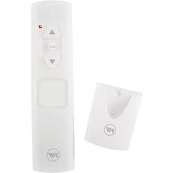
Diaľkové ovládanie Rademacher Rademacher DuoFern Standaard 9491-2 32480361, 1-kanálový
€65.25 Overiť cenu -
Homematic 131775C0 Max. dosah 100 m
€34.32 Overiť cenu -
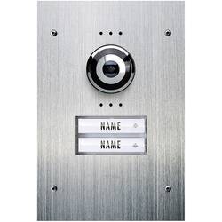
Káblový domové videotelefón m-e modern-electronics VDV 920, nerezová oceľ
€486.10 Overiť cenu