
€53.67
Priemerné hodnotenie:0/5(0x)
Vlastnosti a parametre výrobku
Skúsenosti užívateľov
Otázky a odpovede
Dokumentácia
Popis
Vlastnosti a parametre výrobku
| Séria (domáca technika) | Homematic IP |
|---|---|
| Bezdrôtové zariadenie (Smart Home) | Hersteller-Spezifisch |
| Spôsob ochrany | IP20 |
| Napájanie | Na batérie |
| Prevádzkové napätie | 3 V |
| Frekvencia | 868 MHz |
| Max. dosah | 230 m |
| Spôsob montáže | Pod omietku |
| Vonkajšia šírka | 48.5 mm |
| Vonkajšia výška | 53 mm |
| Rozmer, hĺbka | 15 mm |
| Hmotnosť | 50 g |
| Tok signálu (konektor A na B) | Obojsmerný (bi) |
| Kategória výrobku | Kontaktné rozhranie |
Skúsenosti a názory zákazníkov
- Skúsenosti užívateľov nie sú k dispozícii.
Otázky užívateľov
- Užívatelia k tomuto výrobku zatiaľ nemali žiadne otázky.
Dokumentácia
Podmienky používania dokumentácie
Installations- und Bedienungsanleitung Installation instruction and operating manual Kontakt-Schnittstelle Unterputz – 6-fachS. 2
Contact Interface flush-mount – 6 channelsp. 24
HmIP-FCI6
Lieferumfang AnzahlBezeichnung 1Homematic IP Kontakt-Schnittstelle Unterputz – 6-fach 21,5 V LR03/Micro/AAA Batterien 1Verbindungskabel 1Bedienungsanleitung Dokumentation © 2018 eQ-3 AG, Deutschland Alle Rechte vorbehalten. Ohne schriftliche Zustimmung des Herausgebers darf diese Anleitung auch nicht auszugsweise in irgendeiner Form reproduziert werden oder unter Verwendung elektronischer, mechanischer oder chemischer Verfahren vervielfältigt oder verarbeitet werden.
Es ist möglich, dass die vorliegende Anleitung noch drucktechnische Mängel oder Druckfehler aufweist. Die Angaben in dieser Anleitung werden jedoch regelmäßig überprüft und Korrekturen in der nächsten Ausgabe vorgenommen. Für Fehler technischer oder drucktechnischer Art und ihre Folgen übernehmen wir keine Haftung.
Alle Warenzeichen und Schutzrechte werden anerkannt.
Printed in Hong Kong Änderungen im Sinne des technischen Fortschritts können ohne Vorankündigung vorgenommen werden.
153506 (web) Version 1.0 (11/2018)
1
C
B
A
D
2…
* * *
3
4
6
Inhaltsverzeichnis 1
Hinweise zur Anleitung …7
2 Gefahrenhinweise …7
3 Funktion und Geräteübersicht …9
4 Allgemeine Systeminformationen …10
5 Inbetriebnahme …11
5.1 Installation …11
5.2 Anlernen …13
6 Batterie wechseln …15
7 Fehlerbehebung …16
7.1 Schwache Batterie …16
7.2 Befehl nicht bestätigt …16
7.3 Duty Cycle …17
7.4 Fehlercodes und Blinkfolgen …18
8 Wiederherstellung der Werkseinstellungen …20
9 Wartung und Reinigung …21
10 Allgemeine Hinweise zum Funkbetrieb …21
11 Technische Daten …22
12 Technical specifications …40
7
Hinweise zur Anleitung 1
Hinweise zur Anleitung Lesen Sie diese Anleitung sorgfältig, bevor Sie Ihr Homematic IP Gerät in Betrieb nehmen. Bewahren Sie die Anleitung zum späteren Nachschlagen auf!
Wenn Sie das Gerät anderen Personen zur Nutzung überlassen, übergeben Sie auch diese Anleitung.
Benutzte Symbole: Achtung!
Hier wird auf eine Gefahr hingewiesen.
Hinweis. Dieser Abschnitt enthält zusätzliche wichtige Informationen.
2 Gefahrenhinweise Öffnen Sie das Gerät nicht. Es enthält keine durch den Anwender zu wartenden Teile. Im Fehlerfall lassen Sie das Gerät von einer Fachkraft prüfen.
Aus Sicherheits- und Zulassungsgründen (CE) ist das eigenmächtige Umbauen und/oder Verändern des Geräts nicht gestattet.
Betreiben Sie das Gerät nur in trockener sowie staubfreier Umgebung, setzen Sie es keinem Ein-
8Gefahrenhinweise fluss von Feuchtigkeit, Vibrationen, ständiger Sonnen- oder anderer Wärmeeinstrahlung, Kälte und keinen mechanischen Belastungen aus.
Das Gerät ist kein Spielzeug! Erlauben Sie Kindern nicht damit zu spielen. Lassen Sie das Verpackungsmaterial nicht achtlos liegen. Plastikfolien/ -tüten, Styroporteile etc. können für Kinder zu einem gefährlichen Spielzeug werden.
Bei Sach- oder Personenschäden, die durch unsachgemäße Handhabung oder Nichtbeachten der Gefahrenhinweise verursacht werden, übernehmen wir keine Haftung. In solchen Fällen erlischt jeder Gewährleistungsanspruch! Für Folgeschäden übernehmen wir keine Haftung!
Das Gerät ist nur für den Einsatz in wohnungsähnlichen Umgebungen geeignet.
Jeder andere Einsatz, als der in dieser Bedienungsanleitung beschriebene, ist nicht bestimmungsgemäß und führt zu Gewährleistungs- und Haftungsausschluss.
9
Funktion und Geräteübersicht 3
Funktion und Geräteübersicht In Verbindung mit der Homematic IP Kontakt-Schnittstelle lassen sich potentialfreie Taster mit wenig Aufwand in das Homematic IP System einbinden. Dadurch können konventionelle Taster flexibel mit Homematic IP Funktionen und Geräten nachgerüstet werden, um beispielsweise Licht oder Rollläden intelligent zu steuern.
Dank des kompakten Gehäuses kann die KontaktSchnittstelle flexibel in einer Unterputzdose montiert werden. Vorhandene Schalterdesigns lassen sich ohne zusätzlichen Montageaufwand weiternutzen.
Über die kostenlose Homematic IP Smartphone-App können auch Schalter und Magnetkontakte mit der Kontakt-Schnittstelle verknüpft werden, um eine komfortable Kommunikation per Funk zu ermöglichen.
Dank des Batteriebetriebs ist der Einsatz des Geräts von bis zu 3 Jahren möglich – ein Anschluss an die Stromversorgung ist nicht erforderlich.
10Allgemeine Systeminformationen Geräteübersicht (s. Abbildung 1): (A) Batteriefachdeckel (B) Systemtaste (Anlerntaste und LED) (C) Anschlussleitung GND
(D) Anschlussleitungen IN1
4 Allgemeine Systeminformationen Dieses Gerät ist Teil des Homematic IP Smart-HomeSystems und kommuniziert über das Homematic IP
Funkprotokoll. Alle Geräte des Systems können komfortabel und individuell per Smartphone über die Homematic IP App konfiguriert werden. Alternativ haben Sie die Möglichkeit, Homematic IP Geräte über die Zentrale CCU2/CCU3 oder in Verbindung mit vielen Partnerlösungen zu betreiben. Welcher Funktionsumfang sich innerhalb des Systems im Zusammenspiel mit weiteren Komponenten ergibt, entnehmen Sie bitte dem Homematic IP Anwenderhandbuch. Alle technischen Dokumente und Updates finden Sie stets aktuell unter www.eQ-3.de.
11
Inbetriebnahme 5
Inbetriebnahme5.1 Installation Sollten für die Montage bzw. Installation des Gerätes Änderungen oder Arbeiten an der Hausinstallation erforderlich sein, ist unbedingt folgender Sicherheitshinweis zu beachten: Hinweis! Installation nur durch Personen mit einschlägigen elektrotechnischen Kenntnissen und Erfahrungen!* Durch eine unsachgemäße Installation gefährden Sie- Ihr eigenes Leben; – das Leben der Nutzer der elektrischen Anlage.
Mit einer unsachgemäßen Installation riskieren Sie schwere Sachschäden, z. B. durch Brand. Es droht für Sie die persönliche Haftung bei Personen- und Sachschäden.
Wenden Sie sich an einen Elektroinstallateur!
* Erforderliche Fachkenntnisse für die Installation: Für die Installation sind insbesondere folgende Fachkenntnisse erforderlich:- Die anzuwendenden „5 Sicherheitsregeln“: Freischalten; gegen Wiedereinschalten sichern; Spannungsfreiheit feststellen; Erden und Kurzschließen; benachbarte, unter Spannung stehende Teile abdecken oder abschranken; – Auswahl des geeigneten Werkzeuges, der Messgeräte und ggf. der persönlichen Schutzausrüstung; – Auswertung der Messergebnisse;
12Inbetriebnahme – Auswahl des Elektro-Installationsmaterials zur Sicherstellung der Abschaltbedingungen; – IP-Schutzarten; – Einbau des Elektroinstallationsmaterials; – Art des Versorgungsnetzes (TN-System, IT-System, TT-System) und die daraus folgenden Anschlussbedingungen (klassische Nullung, Schutzerdung, erforderliche Zusatzmaßnahmen etc.).
Für die Installation der Kontakt-Schnittstelle benötigen Sie die mitgelieferten 20 cm-Verbindungsleitungen (0,22
mm²) mit Aderendhülsen. Gehen Sie wie folgt vor:- Entfernen Sie vor dem Anschluss die Gummiabdeckungen, die auf die Aderendhülsen aufgesteckt sind.
– Stecken Sie die Verbindungsleitungen in den Steck-verbinder, bis der Verschluss vollständig einrastet.- Schließen Sie den verwendeten Taster/Schalter/Kontakt gemäß des Anschlussbildes an die Anschlussleitungen GND (schwarz) (C) und IN1
(orange) (D) an (s. Abbildung 2).
Das Gerät kann zusammen mit dem Taster und Schalter in einer Unterputzdose verbaut werden, sofern dort keine potentialführenden Leitungen liegen.
Die Anschlussleitungen des Tasters/Schalters/ Kontakts dürfen nicht länger als drei Meter sein.
13
Inbetriebnahme Es ist strikt darauf zu achten, dass die Anschlussleitungen räumlich getrennt von netzspannungsführenden Leitungen verlegt werden (z. B. in eigenen Kabelkanälen oder Installationsrohren).
Die Kontakt-Schnittstelle ist nur für den Anschluss potentialfreier Taster geeignet.
Verbinden Sie die Anschlussleitungen nicht mit 230 V-Netzspannung!
5.2 AnlernenBitte lesen Sie diesen Abschnitt erst vollständig, bevor Sie mit dem Anlernen beginnen.
Richten Sie zunächst Ihren Homematic IP Access Point über die Homematic IP App ein, um weitere Homematic IP Geräte im System nutzen zu können. Ausführliche Informationen dazu finden Sie in der Bedienungsanleitung des Access Points.
Damit die Kontakt-Schnittstelle in Ihr System integriert werden und mit anderen Homematic IP Geräten kommunizieren kann, muss sie zunächst an den Homematic IP
Access Point angelernt werden.
14Inbetriebnahme Zum Anlernen der Kontakt-Schnittstelle gehen Sie wie folgt vor:- Öffnen Sie die Homematic IP App auf Ihrem Smartphone.
– Wählen Sie den Menüpunkt „Gerät anlernen“ aus.
– Drücken Sie die Verrastung am Batteriefachdeckel (A) ein und öffnen Sie das Batteriefach.
– Ziehen Sie den Isolierstreifen aus dem Batteriefach heraus. Der Anlernmodus ist für 3 Minuten aktiv.
Sie können den Anlernmodus manuell für weitere 3 Minuten starten, indem Sie die Systemtaste (B) kurz drücken (s. Abbildung 3).
– Das Gerät erscheint automatisch in der Homematic IP App.
– Zur Bestätigung geben Sie in der App die letzten vier Ziffern der Gerätenummer (SGTIN) ein oder scannen Sie den QR-Code. Die Gerätenummer finden Sie auf dem Aufkleber im Lieferumfang oder direkt am Gerät.
– Warten Sie, bis der Anlernvorgang abgeschlossen ist.
– Zur Bestätigung eines erfolgreichen Anlernvorgangs leuchtet die LED (B) grün. Das Gerät ist nun einsatzbereit.
– Leuchtet die LED rot, versuchen Sie es erneut.
15
Batterie wechseln – Wählen Sie aus, in welche Anwendung (z. B. Licht und/oder Beschattung) das Gerät verwendet werden soll.
– Vergeben Sie in der App einen Namen für das Gerät und ordnen Sie es einem Raum zu.
6 Batterie wechseln Wird eine leere Batterie in der App bzw. am Gerät ange-zeigt (s. „7.4 Fehlercodes und Blinkfolgen“ auf Seite 18), bzw. erfolgt beim Betätigen des Tasters keine Reaktion des zu steuernden Geräts, tauschen Sie die verbrauchte Batterien gegen zwei neue Batterien des Typs LR03/Micro/AAA aus.
– Drücken Sie die Verastung am Batteriefachdeckel (A) ein und öffnen Sie das Batteriefach.
– Entnehmen Sie die leeren Batterien aus dem Batteriefach.
– Legen Sie zwei neue 1,5 V LR03/Micro/AAA Batterien entsprechend den Polaritätsmarkierungen in das Batteriefach ein (s. Abbildung 4).
Nach dem Einlegen der Batterie führt das Gerät zunächst einen Selbsttest für ca. 2 Sekunden durch. Danach erfolgt die Initialisierung. Den Abschluss bildet die Test-Anzeige: oranges und grünes Leuchten.
16Fehlerbehebung Vorsicht! Explosionsgefahr bei unsachgemäßem Austausch der Batterien. Batterien dürfen niemals aufgeladen werden. Batterien nicht ins Feuer wer -fen. Batterien nicht übermäßiger Wärme ausset-zen. Batterien nicht kurzschließen. Es besteht Ex-plosionsgefahr!
Verbrauchte Batterien gehören nicht in den Haus-müll! Entsorgen Sie diese in Ihrer örtlichen Batte-riesammelstelle!
7 Fehlerbehebung7.1 Schwache Batterie Wenn es der Spannungswert zulässt, ist die KontaktSchnittstelle auch bei niedriger Batteriespannung be-triebsbereit. Je nach Beanspruchung kann evtl. nach kur-zer Erholungszeit der Batterie wieder mehrfach gesendet werden.
Bricht beim Senden die Spannung wieder zusammen, wird dies in der Homematic IP App und am Gerät ange -zeigt (s. „7.4 Fehlercodes und Blinkfolgen“ auf Seite 18).
Tauschen Sie in diesem Fall die leeren Batterien gegen zwei neue aus (s. „6 Batterie wechseln“ auf Seite 15).
7.2 Befehl nicht bestätigtBestätigt mindestens ein Empfänger einen Befehl nicht, leuchtet zum Abschluss der fehlerhaften Übertragung die
17
Fehlerbehebung LED
(B) rot auf. Grund für die fehlerhafte Übertragung kann eine Funkstörung sein (s. „10 Allgemeine Hinweise zum Funkbetrieb“ auf Seite 21). Die fehlerhafte Übertragung kann folgende Ursachen haben:- Empfänger nicht erreichbar – Empfänger kann Befehl nicht ausführen (Lastausfall, mechanische Blockade etc.) oder – Empfänger defekt.
7.3 Duty Cycle Der Duty Cycle beschreibt eine gesetzlich geregelte Begrenzung der Sendezeit von Geräten im 868 MHz-Bereich. Das Ziel dieser Regelung ist es, die Funktion aller im 868 MHz-Bereich arbeitenden Geräte zu gewährleisten.
In dem von uns genutzten Frequenzbereich 868 MHz beträgt die maximale Sendezeit eines jeden Geräts 1 % einer Stunde (also 36 Sekunden in einer Stunde). Die Geräte dürfen bei Erreichen des 1 %-Limits nicht mehr senden, bis diese zeitliche Begrenzung vorüber ist. Gemäß dieser Richtlinie, werden Homematic IP-Geräte zu 100 % normenkonform entwickelt und produziert.
Im normalen Betrieb wird der Duty Cycle in der Regel nicht erreicht. Dies kann jedoch in Einzelfällen bei der Inbetriebnahme oder Erstinstallation eines Systems durch vermehrte und funkintensive Anlernprozesse der Fall sein.
Eine Überschreitung des Duty Cycle-Limits wird durch einmal langes rotes Blinken der LED (B) angezeigt und kann sich durch temporär fehlende Funktion des Geräts
18Fehlerbehebung äußern. Nach kurzer Zeit (max. 1 Stunde) ist die Funktion des Geräts wiederhergestellt.
7.4 Fehlercodes und BlinkfolgenSie können über die Homematic IP App einstellen, ob die Geräte-LED außer während der Konfiguration auch zur Signalisierung des Kommunikationsstatus genutzt werden soll.
BlinkcodeBedeutungLösung Kurzes oranges BlinkenFunkübertragung/Sendeversuch/ DatenübertragungWarten Sie, bis die Übertragung beendet ist.
1x langes grünes LeuchtenVorgang bestätigtSie können mit der Bedienung fortfahren.
1x langes rotes LeuchtenVorgang fehlgeschlagen oder Duty Cycle-Limit erreichtVersuchen Sie es erneut („7.2 Befehl nicht bestätigt“ auf Seite 16 oder „7.3
Duty Cycle“ auf Seite 17).
19
Fehlerbehebung Kurzes oranges Leuchten (nach grüner oder roter Empfangsmeldung)Batterie leer Tauschen Sie die Batterie des Geräts aus (s. „6 Batterie wechseln“ auf Seite 15).
Kurzes oranges Blinken (alle 10 s)Anlernmodus aktivGeben Sie die letzten vier Ziffern der Geräte-Seriennummer zur Bestätigung ein (s. „5.2 Anlernen“ auf Seite 13).
6x langes rotes BlinkenGerät defekt Achten Sie auf die Anzeige in Ihrer App oder wenden Sie sich an Ihren Fachhändler.
1x oranges und 1x grünes Leuchten (nach dem Einlegen der Batterien)Testanzeige Nachdem die Testanzeige erloschen ist, können Sie fortfahren.
20Wiederherstellung der Werkseinstellungen 8
Wiederherstellung der Werkseinstellungen Die Werkseinstellungen des Geräts können wiederhergestellt werden. Dabei gehen alle Einstellungen verloren.
Um die Werkseinstellungen der Kontakt-Schnittstelle wiederherzustellen, gehen Sie wie folgt vor:- Drücken Sie die Verastung am Batteriefachdeckel (A) ein und öffnen Sie das Batteriefach.
– Entnehmen Sie eine Batterie aus dem Batteriefach.
– Legen Sie die Batterie entsprechend den Polaritätsmarkierungen wieder ein und halten Sie gleichzeitig die Systemtaste (B) für 4 s gedrückt, bis die LED (B) schnell orange zu blinken beginnt (s. Abbildung 3+4).
– Lassen Sie die Systemtaste wieder los.
– Drücken Sie die Systemtaste erneut für 4 s, bis die LED grün aufleuchtet.
– Lassen Sie die Systemtaste wieder los, um das Wiederherstellen der Werkseinstellungen abzuschließen.
Das Gerät führt einen Neustart durch.
21
Wartung und Reinigung 9
Wartung und Reinigung Das Gerät ist für Sie bis auf einen eventuell erforderlichen Batteriewechsel wartungsfrei. Überlassen Sie eine Reparatur einer Fachkraft.
10 Allgemeine Hinweise zum Funkbetrieb Die Funk-Übertragung wird auf einem nicht exklusiven Übertragungsweg realisiert, weshalb Störungen nicht ausgeschlossen werden können. Weitere Störeinflüsse können hervorgerufen werden durch Schaltvorgänge, Elektromotoren oder defekte Elektrogeräte.
Die Reichweite in Gebäuden kann stark von der im Freifeld abweichen. Außer der Sendeleistung und den Empfangseigenschaften der Empfänger spielen Umwelteinflüsse wie Luftfeuchtigkeit neben baulichen Gegebenheiten vor Ort eine wichtige Rolle.
Hiermit erklärt die eQ-3 AG, Maiburger Str. 29, 26789 Leer, Deutschland, dass der Funkanlagentyp Homematic IP
HmIP-FCI6 der Richtlinie 2014/53/EU entspricht. Der vollständige Text der EU-Konformitätserklärung ist unter der folgenden Internetadresse verfügbar: www.eq-3.de
22Technische Daten 11
Technische Daten Geräte-Kurzbezeichnung: HmIP-FCI6Versorgungsspannung: 2x 1,5 V LR03/Micro/ Batterie Leistungsaufnahme im Ruhebetrieb: 10 µA
Stromaufnahme: 40 mA max.
Batterielebensdauer: 3 Jahre (typ.) Schutzart: IP20
Umgebungstemperatur: 5 bis 35 °C
Abmessungen (B x H x T): 48,5 x 53 x 15 mm Gewicht: 50 g (inkl. Batterie) Funk-Frequenzband: 868,0-868,6 MHz 869,4-869,65 MHz Max. Funk-Sendeleistung: 10 dBm Empfängerkategorie: SRD category 2
Typ. Funk-Freifeldreichweite: 230 m Duty Cycle: < 1 % pro h/< 10 % pro h Technische Änderungen vorbehalten.
23
Technische Daten EntsorgungshinweisGerät nicht im Hausmüll entsorgen! Elektronische Geräte sind entsprechend der Richtlinie über Elektro- und Elektronik-Altgeräte über die örtlichen Sammelstellen für Elektronik-Altgeräte zu entsorgen.
Konformitätshinweis Das CE-Zeichen ist ein Freiverkehrszeichen, das sich ausschließlich an die Behörden wendet und keine Zusicherung von Eigenschaften beinhaltet.
Bei technischen Fragen zum Gerät wenden Sie sich bitte an Ihren Fachhändler.
24
Package contents Quantity Description 1Homematic IP Contact Interface flush-mount – 6 channels 21.5 V LR03/micro/AAA batteries 1Connecting cable 1User manual Documentation © 2018 eQ-3 AG, Germany All rights reserved. Translation from the original version in German. This manual may not be reproduced in any format, either in whole or in part, nor may it be duplicated or edited by electronic, mechanical or chemical means, without the written consent of the publisher.
Typographical and printing errors cannot be excluded. However, the information contained in this manual is reviewed on a regular basis and any necessary corrections will be implemented in the next edition. We accept no liability for technical or typographical errors or the consequences thereof.
All trademarks and industrial property rights are acknowledged.
Printed in Hong Kong Changes may be made without prior notice as a result of technical advances.
153506 (web) Version 1.0 (11/2018)
25
Table of contents 1
Information about this manual…26
2 Hazard information …26
3 Function and device overview …28
4 General system information …29
5 Start-up …30
5.1 Installation …30
5.2 Teaching-in …32
6 Changing battery …34
7 Troubleshooting …35
7.1 Weak battery …
35
7.2 Command not confirmed …35
7.3 Duty cycle …36
7.4 Error codes and flashing sequences …36
8 Restore factory settings …38
9 Maintenance and cleaning …39
10 General information about radio operation …39
26Information about this manual 1
Information about this manual Please read this manual carefully before beginning operation with your Homematic IP component. Keep the manual so you can refer to it at a later date if you need to.
If you hand over the device to other persons for use, please hand over this manual as well.
Symbols used: Attention!
This indicates a hazard.
Please note: This section contains important additional information.
2 Hazard information Do not open the device. It does not contain any parts that can be maintained by the user. In the event of an error, please have the device checked by an expert.
For safety and licensing reasons (CE), unauthorized change and/or modification of the device is not permitted.
27
Hazard information The device may only be operated in dry and dustfree environment and must be protected from the effects of moisture, vibrations, solar or other methods of heat radiation, cold and mechanical loads.
The device is not a toy; do not allow children to play with it. Do not leave packaging material lying around. Plastic films/bags, pieces of polystyrene, etc. can be dangerous in the hands of a child.
We do not assume any liability for damage to property or personal injury caused by improper use or the failure to observe the hazard information. In such cases, any claim under warranty is extinguished! For consequential damages, we assume no liability!
The device may only be operated within residential buildings.
Using the device for any purpose other than that described in this operating manual does not fall within the scope of intended use and shall invalidate any warranty or liability.
28Function and device overview 3
Function and device overview Floating push-buttons can be integrated into the Homematic IP system with relatively little effort in conjunction with the Homematic IP Contact Interface. This means conventional push-buttons can be retrofitted flexibly with Homematic IP functions and devices so that e.g.
lights and shutters can benefit from intelligent controls.
The compact housing means the contact interface can be mounted flexibly inside a flush-mounted box. Existing switches or switch series can continue to be used without any additional installation effort.
The free Homematic IP smartphone app even allows switches and magnetic contacts to be connected to the contact interface to facilitate convenient wireless communication.
The durable battery has a service life of up to 3 years – the device does not need to be connected to the power supply.
29
General system information Device overview (see figure 1): (A) Battery compartment cover (B) System button (teach-in button and LED) (C) GND connecting cable (D) IN1 connecting cable 4 General system information This device is part of the Homematic IP smart home system and works with the Homematic IP radio protocol.
All devices of the system can be configured comfortably and individually with the Homematic IP smartphone app. Alternatively, you can operate the Homematic IP
devices via the Central Control Unit CCU2/CCU3 or in connection with various partner solutions. The available functions provided by the system in combination with other components are described in the Homematic IP
User Guide. All current technical documents and updates are provided at www.eQ-3.com.
30Start-up 5
Start-up5.1 Installation If changes or works have to be made on the house installation for mounting or installing the device, the following safety instruction must be considered: Please note! Only to be installed by persons with the relevant electro-technical knowledge and experience!* Incorrect installation can put- your own life at risk; – and the lives of other users of the electrical system.
Incorrect installation also means that you are running the risk of serious damage to property, e.g. because of a fire.
You may be personally liable in the event of injuries or damage to property.
Contact an electrical installer!
*Specialist knowledge required for installation: The following specialist knowledge is particularly important during installation:- The “5 safety rules” to be used: Disconnect from mains; Safeguard from switching on again; Check that system is de-energised; Earth and short circuit; Cover or cordon off neighbouring live parts; – Select suitable tool, measuring equipment and, if necessary, personal safety equipment;
31
Start-up – Evaluation of measuring results; – Selection of electrical installation material for safeguarding shut-off conditions; – IP protection types; – Installation of electrical installation material; – Type of supply network (TN system, IT system, TT system) and the resulting connecting conditions (classical zero balancing, protective earthing, required additional measures etc.).
The supplied 20 cm connecting cable (0.22 mm²) with ferrules is required to install the contact interface. Follow these steps:- Remove the rubber caps from the ferrules prior to connection.
– Plug in the connecting cables into the plug con-nector until the connector engages properly.- Connect the push-button/switch/contact in use to the connecting cables GND (black) (C) and IN1
(orange) (D) (see figure 2).
The device can be installed inside a flushmounted box along with a push-button and switch as long as it does not contain any live wires.
The connecting cables for the push-button/ switch/contact must not be longer than three metres.
32Start-up It is absolutely essential to ensure that the connecting cables are laid so that they are physically separate from cables carrying mains voltage (e.g.
in separate cable ducts or wiring conduits).
The contact interface is only suitable for connecting floating contacts.
Do not connect the connecting cables with 230 V
mains voltage.
5.2 Teaching-inPlease read this entire section before starting the teach-in procedure.
First set up your Homematic IP Access Point via the Homematic IP app to enable operation of other Homematic IP devices within your system.
For further information, please refer to the operating manual of the Access Point.
To integrate the contact interface into your system and enable it to communicate with other Homematic IP
devices, you must teach-in the device to your Homematic IP Access Point first.
To teach-in the contact interface, please proceed as
33
Start-up follows: – Open the Homematic IP app on your smartphone.
– Select the menu item “Teach-in device”.
– Press the latches of the battery compartment cover (A) and open the battery compartment.
– Remove the insulation strip from the battery compartment. Teach-in mode remains activated for 3 minutes.
You can manually start the teach-in mode for another 3 minutes by pressing the system button (B) shortly (see figure 3).
– Your device will automatically appear in the Homematic IP app.
– To confirm, please enter the last four digits of the device number (SGTIN) in your app or scan the QR code. Therefore, please see the sticker supplied or attached to the device.
– Please wait until teach-in is completed.
– If teaching-in was successful, the LED (B) lights up green. The device is now ready for use.
– If the LED lights up red, please try again.
– Please select the application (for example, light and/or security) in which the device will be used.
– In the app, give the device a name and allocate it to a room.
34Changing battery 6
Changing battery If the app or device displays an empty battery (see „7.4
Error codes and flashing sequences“ on page 36), or if there is no response from the device in question after pressing the push-button, replace the old battery with a new LR03/Micro/AAA one. – Press the latches of the battery compartment cover (A) and open the battery compartment.
– Remove the empty batteries from the battery compartment.
– Insert two new 1.5 V LR03/Micro/AAA batteries into the battery compartment, making sure that you insert them the right way round (see figure 4).
Once the battery has been inserted, the device will per-form a self-test (approx. 2 seconds). Afterwards, initialisa-tion is carried out. The LED test display will indicate that initialisation is complete by lighting up orange and green.
Caution! There is a risk of explosion if the battery is not replaced correctly. Never recharge standard bat-teries. Do not throw the batteries into a fire. Do not expose batteries to excessive heat. Do not short-cir-cuit batteries. Doing so will present a risk of explosion.
Used batteries should not be disposed of with regular domestic waste! Instead, take them to your local battery disposal point.
35
Troubleshooting 7
Troubleshooting7.1 Weak battery Provided that the voltage value permits it, the contact in-terface will remain ready for operation also if the battery voltage is low. Depending on the particular load, it may be possible to send transmissions again repeatedly, once the batteries have been allowed a brief recovery period.
If the voltage drops too far during transmission, this will be displayed on the device or via the Homematic IP app (see „7.4 Error codes and flashing sequences“ on page 36).
In this case, replace the empty batteries by two new bat -teries (see „6 Changing battery“ on page 34).
7.2 Command not confirmedIf at least one receiver does not confirm a command, the device LED (B) lights up red at the end of the failed transmission process. The failed transmission may be caused by radio interference (see „10 General information about radio operation“ on page 39). The failed transmission may also be caused by the following:- Receiver cannot be reached.
– Receiver is unable to execute the command (load failure, mechanical blockade, etc.).
– Receiver is defective.
36Troubleshooting 7.3
Duty cycle The duty cycle is a legally regulated limit of the transmission time of devices in the 868 MHz range. The aim of this regulation is to safeguard the operation of all devices working in the 868 MHz range.
In the 868 MHz frequency range we use, the maximum transmission time of any device is 1% of an hour (i.e. 36
seconds in an hour). Devices must cease transmission when they reach the 1% limit until this time restriction comes to an end. Homematic IP devices are designed and produced with 100% conformity to this regulation.
During normal operation, the duty cycle is not usually reached. However, repeated and radio-intensive teachin processes mean that it may be reached in isolated instances during start-up or initial installation of a system.
If the duty cycle is exceeded, this is indicated by one long flash of the device LED (B), and may manifest itself in the device temporarily working incorrectly. The device starts working correctly again after a short period (max. 1 hour).
7.4 Error codes and flashing sequencesYou can use the Homematic IP app to make settings including whether the device LED should also be used to signal the communication status, except during the configuration process.
37
Troubleshooting Flashing code MeaningSolution Short orange flashingRadio transmission/ attempting to transmit/data transmissionWait until the transmission is completed.
1x long green lightingTransmission confirmedYou can continue operation.
1x long red lightingTransmission failed or duty cycle limit is reachedPlease try again (see sec. „7.2 Command not confirmed“ on page 35 or „7.3
Duty cycle“ on page 36).
Short orange lighting (after green or red confirmation)Battery empty Replace the batteries of the device (see „6 Changing battery“ on page 34).
Short orange flashing (every 10 s)Teach-in mode activePlease enter the last four numbers of the device serial number to confirm (see „5.2
Teaching-in“ on page 32).
38Restore factory settings 6x long red flashingDevice defectivePlease see your app for error message or contact your retailer.
1x orange and 1 x green lighting (after inserting batteries)Test display Once the test display has stopped, you can continue.
8 Restore factory settings The factory settings of the device can be restored. If you do this, you will lose all your settings.
To restore the factory settings of the contact interface, please proceed as follows:- Press the latches of the battery compartment cover (A) and open the battery compartment.
– Remove one battery from the battery compartment.
– Insert the battery ensuring that the polarity is correct and press and hold down the system button (B) for 4 s at the same time, until the LED (B) will quickly start flashing orange (see figure 3+4).
– Release the system button again.
– Press and hold down the system button again for
39
Maintenance and cleaning 4 seconds, until the LED lights up green.
– Release the system button to finish the procedure.
The device will perform a restart.
9 Maintenance and cleaning The device does not require you to carry out any maintenance other than replacing the battery when necessary.
Enlist the help of an expert to carry out any repairs.
10 General information about radio operation Radio transmission is performed on a non-exclusive transmission path, which means that there is a possibility of interference occurring. Interference can also be caused by switching operations, electrical motors or defective electrical devices.
The range of transmission within buildings can differ greatly from that available in the open air.
Besides the transmitting power and the reception characteristics of the receiver, environmental factors such as humidity in the vicinity have an important role to play, as do on-site structural/ screening conditions.
40General information about radio operation Hereby, eQ-3 AG, Maiburger Str. 29, 26789 Leer/ Germany declares that the radio equipment type Homematic IP HmIP-FCI6 is in compliance with Directive 2014/53/EU. The full text of the EU declaration of conformity is available at the following internet address: www.eq-3.com 12 Technical specifications Device short name: HmIP-FCI6Supply voltage: 2x 1.5 V LR03/micro/ battery Standby power consumption: 10 µA
Current consumption: 40 mA max.
Battery life: 3 years (typ.) Degree of protection: IP20
Ambient temperature: 5 to 35 °C
Dimensions (W x H x D): 48.5 x 53 x 15 mm Weight: 50 g (incl. batteries) Radio frequency band: 868.0-868.6 MHz 869.4-869.65 MHz Maximum radiated power: 10 dBm Receiver category: SRD category 2
Typ. open area RF range: 230 m Duty cycle: < 1 % per h/< 10 % per h Subject to technical changes.
41
General information about radio operation Instructions for disposalDo not dispose of the device with regular domestic waste! Electronic equipment must be disposed of at local collection points for waste electronic equipment in compliance with the Waste Electrical and Electronic Equipment Directive.
Information about conformity The CE sign is a free trading sign addressed exclusively to the authorities and does not include any warranty of any properties.
For technical support, please contact your retailer.
Bevollmächtigter dMes Herstellers: Mfnuffcturerús futhorisMed representftive: eQ-3 AG
Mfiburger Strfße 29
26789 Leer / GERMANYMwww.eQ-3.de Kostenloser Download der Homematic IP App!Free download of the Homematic IP app!
Podmienky používania dokumentácie produktu
Súvisiace produkty
-
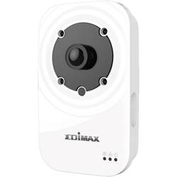
Bezpečnostná Wi-Fi kamera Edimax IC-3116W, denný aj nočný záznam, 1280 x 720 px
€65.25 Overiť cenu -

Vreckový alarm X4-LIFE 701149, 120 dB
€6.53 Overiť cenu -
Prepojovací konektor Rademacher Rademacher DuoFern DuoFern 9472 35001164
€72.97 Overiť cenu -
Rademacher Rademacher DuoFern RTFS 06/28 SW40 4015K-05 26400665
€204.25 Overiť cenu